About
The Journey
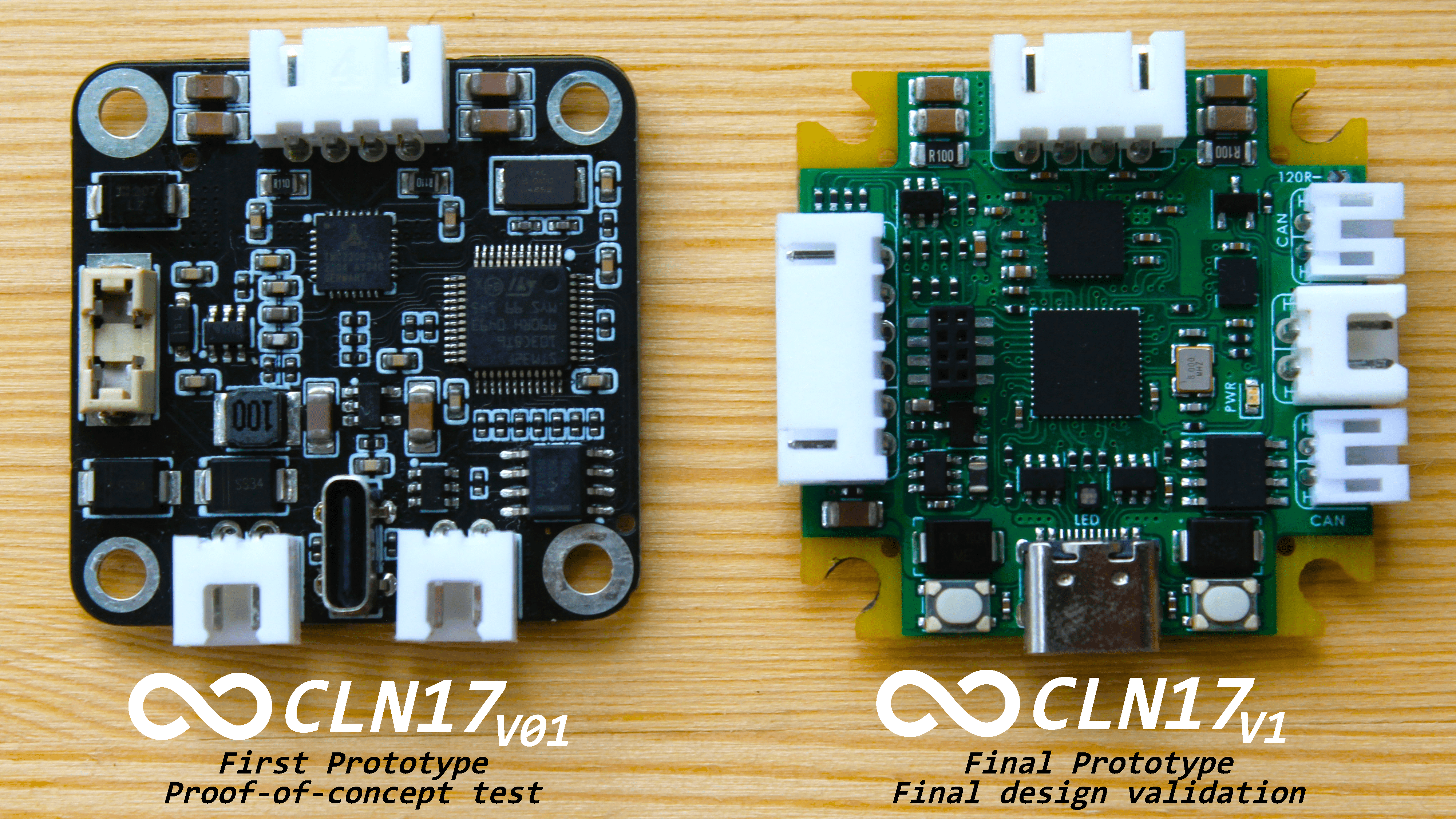
Concept Prototype
In March 2022, while working on a laboratory robot designed for handling test tubes, the idea of using a closed-loop driver came up. This driver needed to be:
- Compact
- Feature minimalistic wiring
- Offer precise and repetitive positioning
- Exhibit unwavering reliability
Sadly, no existing solutions fit the bill. Some were inadequate due to size, others lacked the necessary features or interfaces, some had proprietary code that disallowed modifications, and still, others were either unavailable due to component shortages or had been discontinued. A detailed comparison of these alternatives can be found here.
Thus, a new vision was formed: To create a universal, powerful, and affordable driver that would address all challenges related to controlling a stepper motor.

By September 2022, the first prototype driver was born. Key components included:
- Standard CAN-Bus and USB2.0 with QC support
- STM32F103 MCU
- TLE5012B encoder
- TMC2209 stepper motor driver
However, there were critical setbacks. While it did feature a Type-C port, it relied on Quick Charge (QC) for power, which hampered its flexibility. Another significant limitation was that the controller could not operate the USB and CAN-Bus simultaneously, leading to developmental troubles. A few minor problems arose but were quickly fixed with a soldering iron.
Predictably, this prototype did not achieve all its intended functions, underscoring the need for a revised driver version. This initial setback only strengthened the determination to design a comprehensive stepper motor control solution.
Concept Challenges
Based on the experience and ideas acquired during the prototype development, a final vision of the project and its functionalities has been formed. Below are the key challenges:
- Quiet yet Robust Driver: Designed to deliver core motor control functionalities unhindered by hardware constraints. This driver is intended to be an off-the-shelf solution to minimize the computational load on the microcontroller and mitigate risks, leveraging the inherent safety features of pre-built solutions.
- Support for Standard Interfaces: Incorporates USB for computer connectivity, CAN-Bus for communication within industrial systems, Stepstick for compatibility with legacy systems such as 3D printers, and UART and I2C for interactions in embedded environments.
- High-Speed Microcontroller: Equipped to handle concurrent tasks such as position calculations, real-time encoder-based position monitoring, processing of external commands from various interfaces, and other user-defined tasks.
- Compatibility with Expansion Boards: Ensures the provision to integrate additional boards to accommodate any functionalities not originally addressed.
- Efficient Power Delivery: Guarantees compatibility with widely-used power sources or power banks.
- Optimal Protection: Shields against potential hazards like electrostatic discharges, current overflows, voltage spikes, and more.
- Integrated IMU: Facilitates the detection and compensation of resonances or vibrations while continuously tracking the current position.
- Compact Design: Crafted to seamlessly integrate into devices where space is a constraint.
- Cost-Effective and Modular Structure: Tailored for swift customization based on specific requirements.
There are many other smaller nuances that can be enumerated, but more on that later! You can also read the foundational principles to get a clearer picture.
Functional Prototype
After an extensive development process which involved numerous design iterations and reconsideration of implementation methods, the updated project version that encompasses all concept ideas has been released!
Compared to the previous version, the PCBA is more:
- Compact
- Powerful
- Functional
- Equipped with numerous safety features
It has now evolved from being just another driver to becoming a powerful tool for education, development, testing, and system modeling.
Does it work? The short answer is yes. However, diving deeper, things get a bit more complicated.
From a hardware perspective, there are a few minor issues, which fortunately don't have an impact on the primary functionality. These known issues include:
- Incorrect polarity of the power indicator LED;
- Not stable behavior of the buck DCDC converter at voltages below 6V
Apart from these, all other driver functions operate correctly.
On the code side of things, it's a different story. A vast amount of work is still needed to release the complete driver control library that would unlock its full potential. But there's hope that it's just a matter of time.