Closed-Loop Operations
A closed-loop control system is most easily understood in the context of an automatic control system (ACS), as it is a specific kind of ACS.
Automatic Control System Model
An automatic control system constitutes an intricate network of interlinked components — external influences, sensors, controllers, and actuators. These components collaboratively operate to guide a system towards a defined state or output.
The four key constituents of the ACS are:
- External Influence: Factors affecting system behavior, such as physical quantities or operator commands.
- Influence Sensors: Monitor external influence and system response, providing feedback for adjustments or corrections.
- Controller: Analyzes input from influence sensors and calculates control actions.
- Actuating Device: Executes control actions based on controller input and desired output, performing physical changes.
Closed-Loop system components as ACS
By considering the closed-loop motor driver as a control system, it is possible to identify its key elements and functions.
- External Influence: Unpredictable changes in operating load, supply voltage, travel speed, and position.
-
Influence Sensors: Provide feedback on motor condition and performance.
- Absolute Magnetic Encoder: Measures motor shaft position and rotation speed.
- Current Sensor: Monitors motor current consumption dynamics.
- Accelerometer: Detects motor vibration and system acceleration.
- Controller: MCU that processes sensor data and adjusts motor driver output accordingly.
-
Actuating Device:
-
Motor Driver: Controls motor operation by regulating its power, speed, direction, and position.
- Motor: Converts electrical energy into mechanical motion.
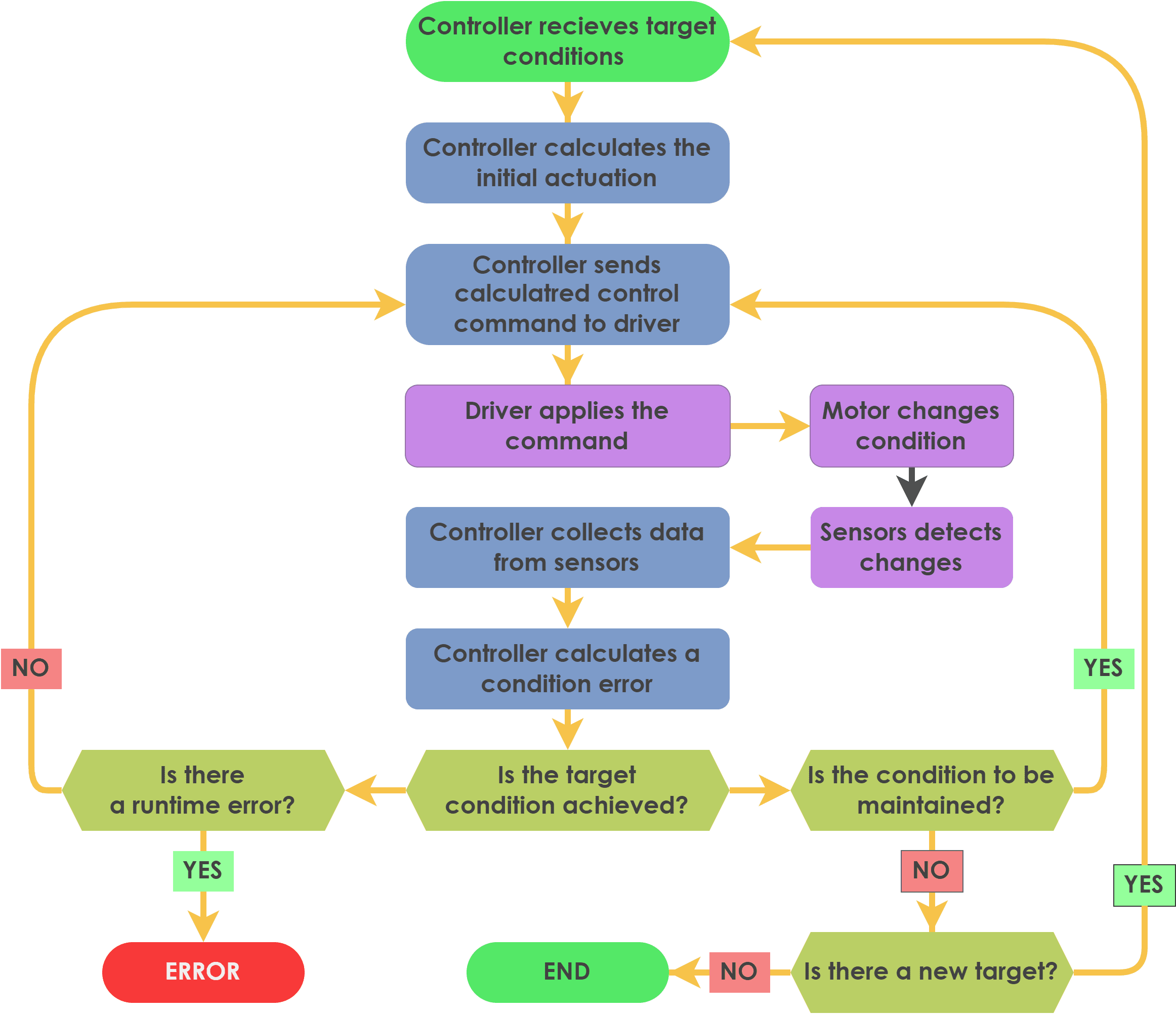
Control Algorithm
The closed-loop motor control system strives to sustain optimum motor performance while adhering to necessary operating conditions like torque, position, speed, and motion direction. This process involves the following steps:
- The controller receives a target position, speed, or torque from an external source.
- The controller obtains sensor data, calculates the discrepancy between the desired and actual motor conditions and performance.
- The control algorithm adjusts motor commands to minimize the error and optimize motor operation.
- The motor driver implements the updated commands to the motor.
- This process continues iteratively, enabling real-time adjustments and optimization until the target conditions are achieved.
Common Error-Correction Strategies
The closed-loop system uses algorithms to correct errors and optimize motor operation. These algorithms include:
- Proportional-Integral-Derivative (PID) control: Balances the motor's response to errors by adjusting the proportional, integral, and derivative gains.
- Model Predictive Control (MPC): Predicts future motor behavior based on a mathematical model and optimizes control actions accordingly.
- Adaptive Control: Adjusts controller parameters in real-time to adapt to changing system dynamics.