System Powering
Supply Sources
The CLN17 operates within a 5-25V range, which is protected by a 26V surge protection TVS diode. While the TMC2209 driver recommends a 6-29V power range, operations with less than 500mA current can work at 5V.
There are 3 options available for powering the driver:
- USB Type-C Connector: Default 5V 3A, can support up to 20V 3A (5A peak) with Power Delivery.
- XH2.5 2Pin POWER Connector: Accepts a 5-25V power source, with a maximum 3A (2.5ARMS recommended).
- XH2.5 6Pin CONTROL connector with power lines: Accepts a 5-25V power source, with a maximum 3A (2.5ARMS recommended).
Operating near the lower limit of the supply voltage
The 5V supply voltage is sufficient for low-power operations with total coil currents lower than 500mA.
At least a 6V supply voltage is required for safe operation at the maximum permissible currents.
Connectors Interconnection
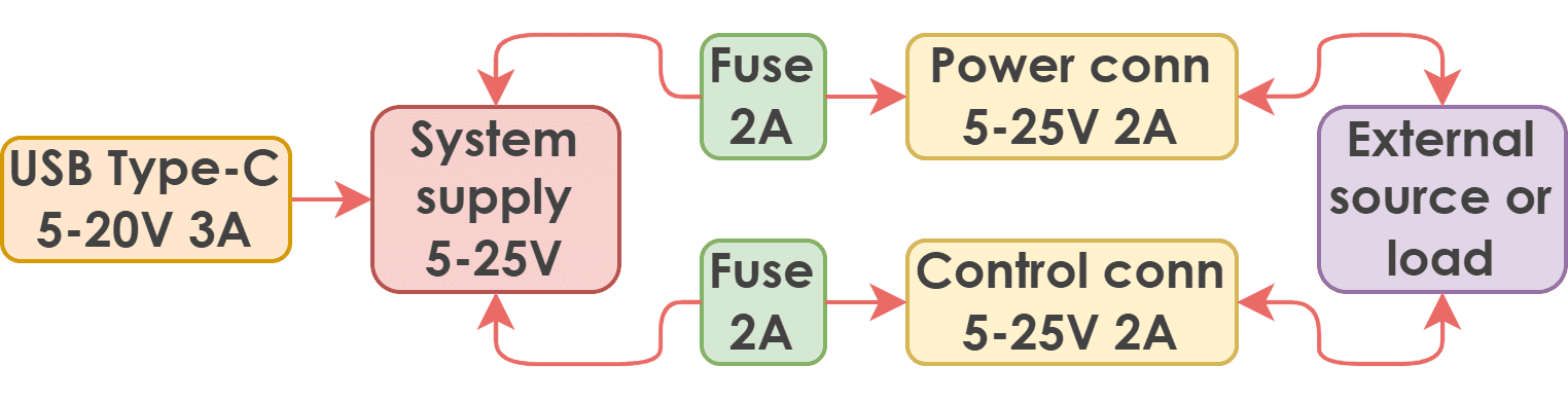
The USB Type-C and power connectors (both XH2.5) are connected in parallel. Each XH2.5 connector is equipped only with a protective resettable fuse rated at 2A, while the USB Type-C has only a protective diode. Therefore,
- The USB Type-C can provide power to the system up to 20V 3ARMS (5A peak).
- Each one at a time XH-2.5 can provide power to the system up to 25V 2A.
- Current transit from USB Type-C to any of the XH2.5 connectors is also possible with a current of up to 2A.
- Current transit from one XH-2.5 to another is possible with a current of up to 2A.
Simultaneous use of power sources
To avoid damaging the power supply, do not connect two different voltage sources to the XH2.5 connectors or apply power to the USB Type-C and XH2.5 connectors simultaneously, if the USB voltage is higher than the XH2.5 connector's voltage (VXH < VUSB).
The maximum current rating of a fuse
The maximum current rating of a self-resetting fuse decreases with rising ambient temperature. For example, at 25°C, the fuse can carry up to 2A, but at 85°C, the maximum current drops to 0.8A.
This power architecture allows flexible and efficient power distribution across a device network. For example, with 7.5W motors (like Nema17 34mm body length), you can power the driver through a USB Type-C 20V 3A connection, and the POWER connector can supply five similar motor assemblies.
Network driver connection
When connecting additional drivers, it is crucial to ensure that the total current passing through the connector at any given moment does not exceed 2A. This limitation allows for a greater number of drivers to be connected, as long as they are not all operated simultaneously.
For powering the network of drivers, it is highly recommended to use a star topology instead of a linear one. Excessive transitions through the drivers should be avoided as they can result in unnecessary heat losses.
Powering expansion boards
The EXPANSION connector's optional configuration allows the driver to power expansion boards or, to a limited extent, be powered by them. However, the maximum current for this setup is limited at 0.8A by the connector, regardless of system voltage.
EXPANSION connector limitations
Ensure that the EXPANSION connector's power lines have 0.8A current protection on the expansion board. Failure to do so can overload the connector, causing irreversible board damage