Enclosure Details
The CLN17 design provides enclosure in three assembly configurations, each involving two components.
Enclosure Manufacturing
Prior to manufacturing the housing, ascertain that the manufacturer supports the following process:
- Material: Aluminum Alloys 6061, 5083, or 7075.
- Minimum milling volume: 45x45mm, with a thickness up to 10mm.
- Milling Technology: 3-axis milling on both sides.
- Minimum tolerances and end mill dia: XY tolerance ≤ 0.075mm, Z tolerance ≤ 0.025mm, end mill diameter ≤ 2.0mm.
- Postprocessing: Threading of 2xM3 threads to a depth of 3mm, chamfering, comprehensive anodizing (preferably black).
Enclosure Parts Types and Principles:
Regardless of the type, enclosure parts share common design principles:
- Connector cut-outs are necessary to avert short circuits.
- Each part should serve as a heatsink or heat distributor from the driver chip, requiring a 0.15mm thermally conductive gasket or tape between the PCB or driver chip and the enclosure's internal protrusion.
Further, there is three types of enclosure parts:
- BASE PART (4mm height): Anchors PCB, maintains shaft and encoder alignment, and facilitates heat transfer from the driver chip to the motor body.
- TOP FLAT PART (3.5mm height): Provides minimal board protection and heat distribution.
- TOP HEATSINK PART (6mm height): Ensures durable board protection and effective heat distribution and dissipation.
Custom Enclosures
These enclosure configurations are merely illustrative. Custom enclosures, adhering to the provided guidelines, can be constructed.
Sealing of Enclosure
If required, the internal part of the enclosure can be sealed for moisture protection or resistance to severe environmental conditions. Avoid filling thermal contact surfaces to prevent driver overheating. Enclosure geometry may also be adjusted to ease the filling process.
Minimum Enclosure configuration
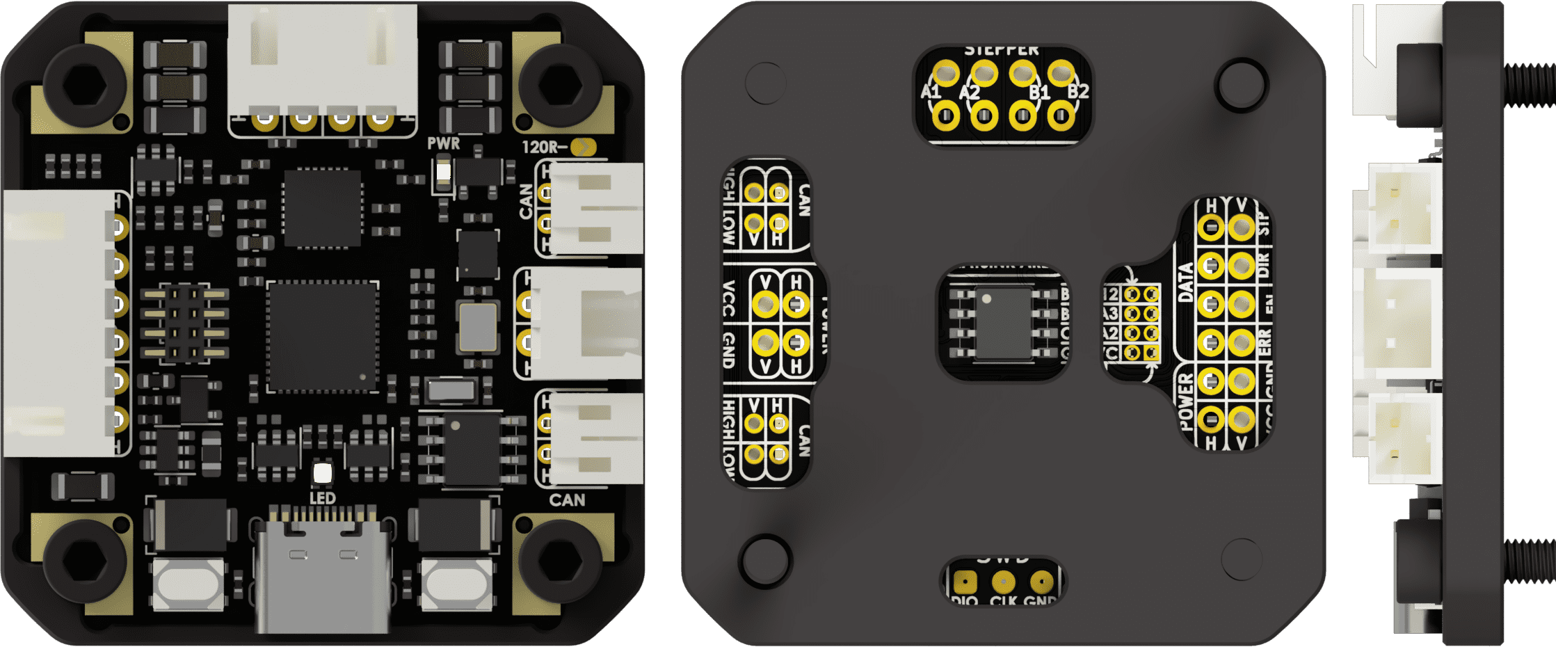
The simplest configuration uses only the BASE PART, providing a compact and cost-effective enclosure.
For high-power operations, an external radiator should be installed on the driver chip.
Fasteners: DIN912 M3x4mm 2pcs to secure board; DIN912 M3xLmm 2pcs (L = motor body length) to secure assembly.
Total dimensions: 42x42x6.5mm.
Total weight: board weight + 8 grams.
Compact Full Enclosure configuration
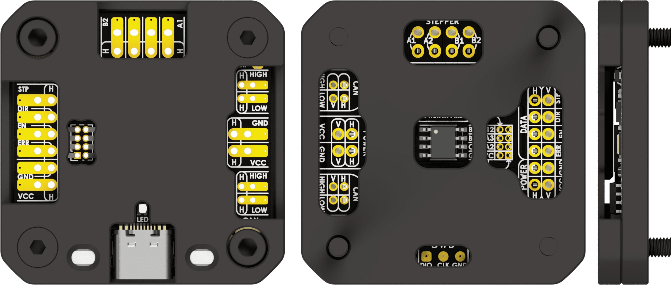
Compact full enclosure configuration that uses both BASE PART and TOP FLAT PART is Ideal for applications where device height is critical but full mechanical protection is required.
This version enhances heat distribution from the driver via a large termal contact area between the enclosure and the driver on both sides.
A board without connectors is recommended for dimension minimization.
Fasteners: DIN7991 M3x6mm 2pcs to secure board between housing parts; DIN912 M3xLmm 2pcs (L = motor body length) to secure assembly.
Total dimensions: 42x42x7.5mm.
Total weight: board weight + 13 grams.
Full enclosure with Heatsink configuration
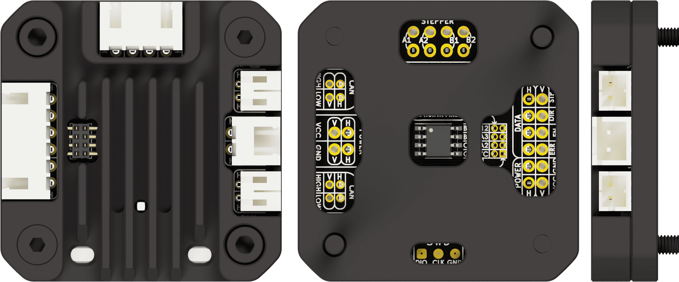
Full enclosure with heatsink configuration that uses both BASE PART and TOP HEATSINK PART is the most effective for heat distribution, dissipation, and mechanical protection.
The extensive heatsink and thermal contact area ensure superior heat management without altering the external dimensions of the enclosure.
It is primarily designed for horizontal connectors, but can also accommodate vertical ones.
Fasteners: DIN7991 M3x10mm 2pcs to secure board between housing parts; DIN912 M3xLmm 2pcs (L = motor body length) to secure assembly.
Total dimensions: 42x42x10mm.
Total weight: board weight + 18 grams.