Board Details
The PCB (Printed Circuit Board) manufacturing process includes two steps: PCB fabrication and component assembly, yielding a PCBA (Printed Circuit Board Assembly).
PCB Manufacturing
Before beginning PCB production, confirm the following board specifications with the PCB manufacturer:
- Layers and board thickness: A 4-layer printed circuit board with a thickness of 1mm.
- Copper: Outer layer copper thickness ≥ 1 oz/ft², inner layer copper thickness ≥ 0.5 oz/ft².
- Minimum tolerances: trace width ≤ 0.127mm, trace spacing ≤ 0.127mm, plated through-hole spacing ≤ 0.254mm, plated through-hole size ≤ 0.3mm/0.5mm.
- Surface Finish: ENIG (recommended) or Lead-Free HASL.
Panelization
To reduce the cost of mass production for both PCB and PCBA, panelization can be used.
Optimal panelization includes 2x2 (81x81mm), 2x3 (81x124mm), 3x3 (124x124mm), 3x4 (124x167mm), or 4x4 (167x167mm) boards. These dimensions not include additional elements required for production. Larger panels are not reccomended due to increased production costs.
Panelization type recomendation
Include a 5mm gaps between boards in the panel as connectors extends beyond each board's outline.
V-Cut separation of boards is advised.
PCBA Manufacturing
The PCBA is designed for assembly on both sides. The boards have four P&P machine tooling holes at the corners with a diameter of 1.152mm and copper and solder mask clearances of 0.3mm and 0.175mm respectively.
The board design aims for cost-effectiveness and versatility, allowing a highly flexible set of configurations for interfaces, connectors and features without needing a PCB design change. All options are independent and can be selected based on specific needs unless otherwise noted.
Automated assembly can be single-sided or double-sided, each with appropriate configuration options.
Cautions for Component Omission
When omitting components from the board, refer to the schematic. Components and blocks labeled as "optional" can be removed without impairing the system's functionality.
Top Side Assembly
Only an automated assembly is suggested for the PCB top side due to difficult to solder components like 0402 form factor resistors.
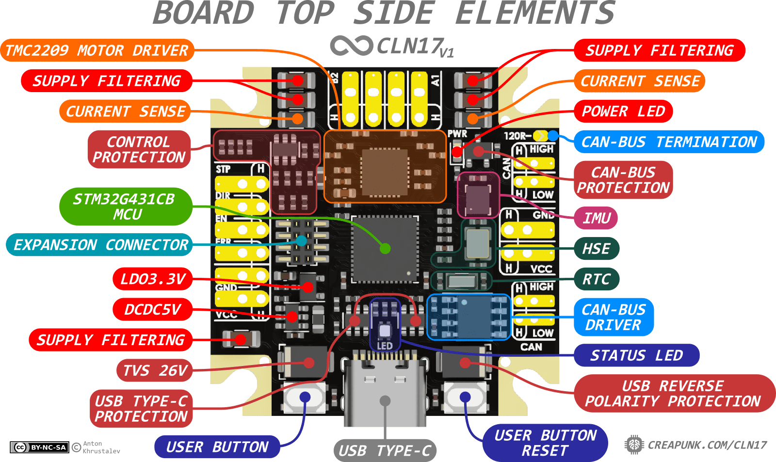
Top Side Assembly Options
The following elements can be omitted from the maximal configuration version based on the specific requirements.
- USB Type-C connector: USB Type-C connector, USB Type-C ESD protection, and USB Type-C reverse polarity protection diode.
-
LEDs: Power LED and its current-limiting resistors, RGB status LED, and its three current-limiting resistors.
-
Buttons: Only the user tactile buttons can be omitted.
- HSE and LSE crystals: HSE crystal with 2 load capacitors and 1M shunt resistor, LSE crystal with 2 load capacitors.
- IMU: IMU and its power filtering capacitor.
- POWER Interface: POWER connector and its fuse on the bottom side.
- CONTROL Interface: CONTROL connector, CONTROL ESD protection, its pull-up and current-limiting resistors, its fuse on the bottom side.
- CAN-Bus Interface: CAN-Bus connector, CAN-Bus driver, its decoupling capacitor, its Zero-Resistor, CAN-Bus ESD protection, and termination resistor. The CAN-Bus driver can support CAN-FD or not.
If an EXPANSION connector is required, automated top-side soldering of an SMD 2x4P1.27mm Pin Socket version is recommended.
CONTROL, POWER, MOTOR and CAN-Bus interfaces wires can be directly soldered to the board.
Bottom Side Assembly
In order for single-sided automated assembly, three components with extended contact pads and termal relief on the board's bottom side should be manually soldered:
- Magnetic Encoder in SOIC-8 package;
- Two Resettable Fuses in 1812 package.
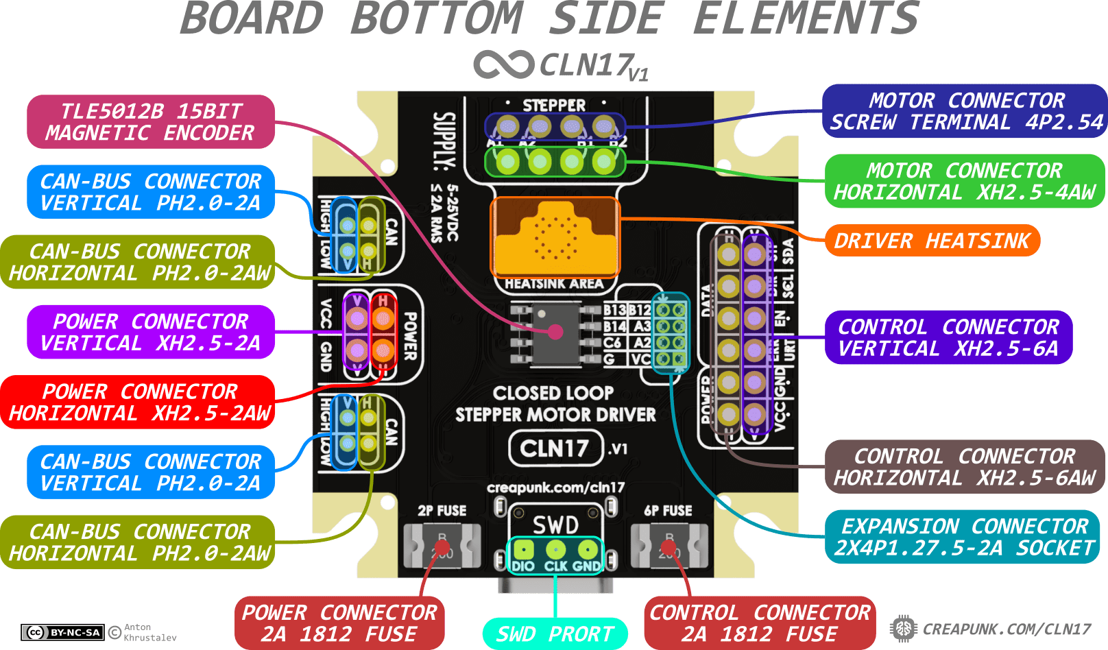
Bottom Side Assembly Options
If connector installation is required, Through-Hole connectors can also be soldered on the board's bottom side (though installed from the top). They can be soldered manually and should only be installed if their interfaces are in use. They can be installed in several configurations.
-
CONTROL 6P Connector: horizontal (XH-6AW) or vertical (XH-6A) orientation.
-
POWER 2P Connector: horizontal (XH-2AW) or vertical (XH-2A) orientation.
-
CAN Connector: horizontal (PH-2AW) or vertical (PH-2A) orientation.
-
EXPANSION Connector: 2x4P1.27mm Pin Socket in Through Hole or SMD (top-side) version.
-
MOTOR Connector: horizontal connector (XH-4AW) or 4P screw terminal with a 2.54mm contact pitch (e.g., XY308-2.54-4P).
Cautions for Soldering Connectors
The maximum length of the soldered leads should be less than 2.5mm to avoid a short circuit with the motor casing.
When installing vertical or horizontal connectors, the connector should be fitted into the set of holes corresponding to the connector type (V = Vertical, H = Horizontal).
Minimum Power and I/O Connections Requirements
The board must be connected to at least one power source (USB, POWER, CONTROL, or EXPANSION) and one I/O interface (USB, CONTROL, CAN-Bus, or EXPANSION).